
DIY Electronic Timer with LED Displays for under $100
First, I would like to say thanks to this community for the inspiration to build my own diecast racing track. I spent the week prior to Christmas building this track for my two sons (and my daughter likes it more than my wife might prefer too!) and it was certainly a hit when they found it stretching through the kitchen and dining room Christmas morning.
Pretty early on, I had my mind set on using some kind of electronic finish line. When it came time to figure out what exactly to use, I couldn’t justify the cost of the commercially available systems (I.e Microwizard, JUDGE, etc.) and, as I learned long ago from my other hobbies, I figured I could build a much cheaper, and maybe better, solution with all the same features.
To try and give a little back to the community, and maybe convince a few that electronic timing won’t break the bank, I thought I would show how I built my four lane electronic timer for about $100. This timer has the ability to display individual lane finishing order and times (four digits) and transmit these times to connected PC (with 0.0001 sec resolution, though I believe the tolerances in the placement of IR LED’s and phototansistros is probably the weak link at this point). I think a comparable kit from Microwizard would cost around $350. I believe you could also probably build something comparable to the JUDGE timer (including PC interface) by substituting single LED’s for the displays for well under $50 (maybe even as cheap as $25 using and Arduino clone and parts you might already have around).
Anyway, enough with the rational, and on to the details. At the heart of this project is an Arduino microcontroller. Just about any Arduino could probably be made to work as we are using fairly little I/O and resources. I happened to have an Arduino Uno laying around unused from another project which made this all the more attractive an option. The use of an Arduino means this timer can run in “stand alone” mode without requiring a PC as some of the other cheap timing options I found/considered would.
Due to the time crunch and because there was no need for reinventing the wheel, I bought a shield from David at miscjunk.org (http://www.miscjunk.org/mj/pg_pdt.html) that on top of providing breakouts for the critical I/O also contains some useful additions like a button to reset the timer, status LED, trim pot for setting the LED display brightness and installation points for the current limiting resistors. If I had more time, I might have built a custom board (and I am still considering doing so if free time allows) but his will certainly get you a functional timer very quickly.
I am running the Arduino code from miscjunk pretty much as is for now. I haven’t tried it, but he says it is even compatible with the GrandPrix Race Manager software that seems pretty popular with the pinewood derby crowd and certainly could be used here as well. As you might have guessed, however, I figured I could build it cheaper (I like a good challenge so we won’t consider what my time is worth) and better (i.e. usable by my young children), so I threw together a quick program to record and display the lane times on a PC.
I used the Adafruit 7-segment I2C driven displays suggested on miscjunk as it just makes it dead simple to run multiple displays, albeit at a pretty significant cost (nearly half the project total in this case). You could definitely do this cheaper if you have more time and the drive to do so. Maybe another good place for a custom board…
In summary, here are the majority of the parts needed:
Arduino Uno - $30 (or $11 for a clone)
Both the original and clone are available many sources. Maybe try to save on shipping by buying it from the same place you get other items.
PDT Timer Shield - $23
Here: http://www.miscjunk.org/mj/pg_pdt_pcb1.html
Adafruit 0.56" 4-Digit 7-Segment Display w/I2C Backpack - $10 per lane
There are multiple colors to choose from but I went with the red ones: http://www.adafruit.com/products/878
I actually bought mine here because they had a pre-Christmas sale and shipping was cheaper: http://chicagodist.com/products/adafrui ... ckpack-red
Infrared LED’s - $4
You could use a multitude of different parts here, including white LED’s as described at miscjunk because they put out enough energy at the wavelengths “visible” to some IR phototransistors to still work, but I preferred not having the visible light and used these: http://www.ebay.com/itm/20-x-Infrared-L ... 383wt_1034
Infrared Phototransistors - $4
Again, you could substitute a multitude of parts here but I used these: http://www.ebay.com/itm/10-x-Photo-Tran ... 442wt_1125
I bought some LED bezels ($4) to make mounting the LED’s a little easier but this is not required. I used these: http://www.ebay.com/itm/20-x-5mm-Bezel- ... 441wt_1125
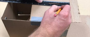
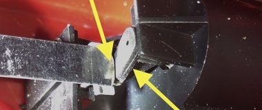
The only other things you should need are a micro switch for the start trigger (I had one laying around) that you will need to adapt to your own starting gate design, some wood or other material to build the timer bridge for holding the IR LED’s and displays (hopefully left over from your track build or other projects) and some cabling and other miscellaneous parts to get everything wired up. Hopefully this isn’t more than another few $.
So all told, by my calculation, we are just under $100 for a two lane timer using an authentic Arduino and only $20 more than that for the four lane timer I built. Substitute an Arduino clone (or parts you already have around) and you can build either for less than $100.
Hopefully this inspires someone else to add electronic timing to their track and a rough guide for how to do it. Please feel free to ask any questions you have.
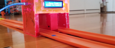
Here are a few pictures to show you how it all looks in action. If you have more than the hand saw and drill I was working with, you could probably make it look a lot nicer than mine as well
Starting Gate
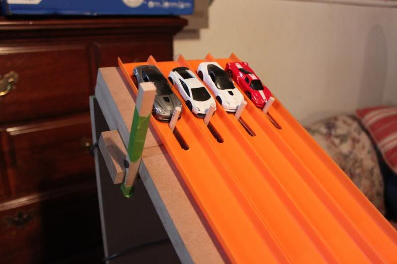
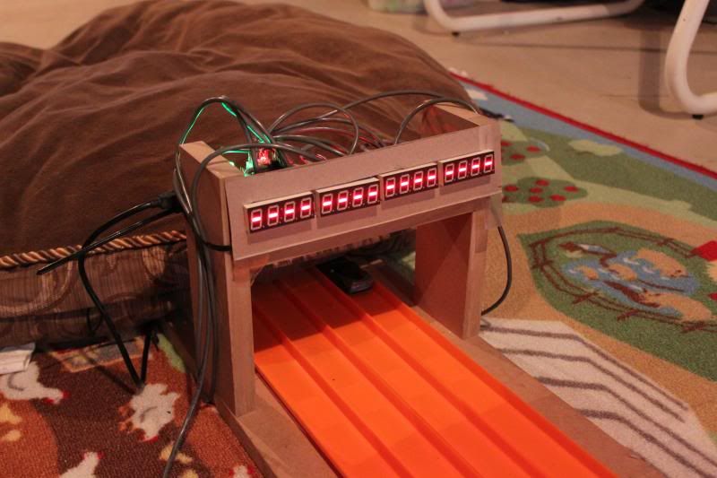
Finish Ready State
Finish Order
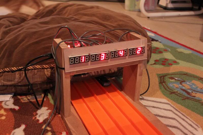
Finish Times

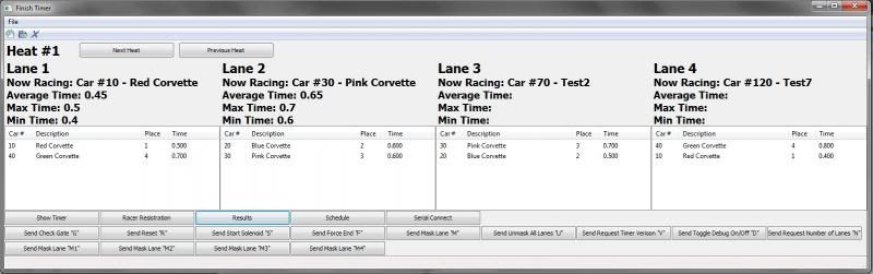
Current state of the PC software (please ignore the unrealistic times and button mess…these are just for testing)
Discussion
I agree with Smitty....most of this is above my skill set.
But I understand it, great write up and information!
Welcome aboard fellow Michigander. Now lets go racing!
I agree with Smitty....most of this is above my skill set.But I understand it, great write up and information!
Welcome aboard fellow Michigander. Now lets go racing!
I would be willing to bet that if you can build your own track, you can successfully tackle this timer build as well. Some basic soldering is likely the only thing outside most folk's skill set, but that can be very easily taught/learned as I proved last week with my oldest son.
P.S. It looks like I am just up the road from you in Hartland...now you really don't have any excuse not to be able to do it
Cool builds and set up. Has it held up to moving it around? Also like that you choose two Corvette ZR1s for your starting gate photo!
Also like that you choose two Corvette ZR1s for your starting gate photo!
Of course you do
Cool builds and set up. Has it held up to moving it around? Also like that you choose two Corvette ZR1s for your starting gate photo!
It has only had to move from the basement where it was built up to the kitchen and back down to its current home once at this point, so it is not much of a test, but so far so good. I built the timer bridge into a 23" long board that has the final piece of segmented track for each lane semi-permanently mounted to it. You can simply detach these last track sections and carry the entire assembly wherever needed. I have no doubt this would stand up perfectly well for real traveling if needed.
And yes, the kids have a bit of an affinity for Corvettes no doubt due, at least in small part, to Dad's job
[ Dad's job
Which team? If you dont want to make it public, you can PM me...
This is super cool...awesome. I'm glad you have come to help us out with getting a timer like this setup...very good & looking forward to more of your post.
Preacher