
Build journal: Himalaya Pass
Hi there,
First of all, i hope you all found your way through 2020, healthy and without too much misery. For me personally it was a really challenging year and diecast racing (unfortunately) wasn't a priority. But i needed some distraction now and then, and some late night track building really helped me to relax and put the stress away. So i like to share the fun with you all.
Secondly, this is my second track builing topic and this time i choose to use ordinary orange track to build a nice, good looking, two track for me and my 10 year old son to play with. In 2018 i build my first 4 lane blu track, which we still use (again) with lots of good races. It performs really well, but takes some time to build up and uses quite some space to store, so i made a plan for something more easy to play with.
I finished this track last month, but i will take you through the steps i took along the way. It might be useful to you (or not ;) I'll try to complete this journal the coming weeks, with all the good and the bad things that happened along the way. Oh, and before you start reading any further: my apologies for any mistakes in language, i'm from the Netherlands so i'll try my best. If you have any questions, please do ask, i'm happy to answer them.
Discussion
Turn 3: Finishgate housing & theme
Now that the electronics work, it's time to come up with an idea for the colors and looks of the track. After a long and exhausting drinking session, the following came up: Mountain -> Snow -> Himalaya pass. So there it was. The orange track would look really nice on a white base, and it sounded kinda catchy. It was a good night.
Anyhow, next up: the housing of the finishgate. I choose to use some leftover pieces of wood an some cheap hardboard (that what we call it, or HPF). After coming up with the right measurements for width and maximum height, i used a jigsaw to cut out the windows for the displays. Next to the gate comes the electronic box, which was actually a bit small. But with some gentle violence, everything fitted perfecty.


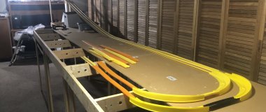
Round 4: Base of the track
At this point i started to need a base for the gate and the actual track, and i wanted to try something out. You know... i really do not like it when the walls of orange trackparts do not line up properly, so i came up with this idea: When you squeeze the trackwalls a tiny eenie weeny little bit (and can keep them under a light constant pressure), all the walls will line up perfectly.
EDIT: Because this track is not permanent and lies only for a day, the light pressure won't distort the track permanently. So when the track is build up again, the trackparts are not squeezed or bent out of shape, and will line up perfectly again under the light pressure. Be careful when you keep the trackparts under stress for a long period of time though!
Shopping list: some medium density fibreboard and and some wooden bars. Got it! Measure the width of the track, glue the bars to the MDF base, and keep the space for the track just 1 mm smaller. Check!

Ok, 1 important thing here! As you see, i used two different kinds of wood and one is not painted. Big differences in air humidity or moisture inside the wood can cause a bended base plate! (I cried for two days when this happened after painting and glueing) So be sure to think about this, let the wood dry together at room temperature and/or paint it all to keep its humidity steady.
To keep the "lighty squeezed" track in place, i somehow used something i read somewhere (uhu). I honestly can't remeber where it was, maybe even here on RDL forum, but all the credits to the person who came up with this:

So i borrowed the idea and turned it into this:


Why the sleeves in the middle of the base you ask? They are necessary, otherwise you can't push-in the track connectors to take the track apart!
And of course, a baseplate for the finishgate, with holes for assembly and the fototransistors:

- So how did you do all the washers? Superglued them together? And yes, I think you read it here somewhere - I read the same thread. — SpyDude
- First of al I gave them a good rub with some sandpaper to smoothen things out. After some good cleaning I did use super glue, indeed. They are nog going anywhere soon. — DDRacer
I'm really enjoying this build log! Keep it up
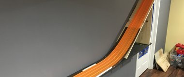
Day 5: The hill & transition
Plenty of time today and i'm enjoying myself pretty well, so let's continue the story.
As said before, the track needed to be simple to set up and it had to be easy to store, so it's time to go (online) shopping again. This time i needed one long bolt with a wingnut and one special hinge. Found two pieces of wood, a small piece of iron plating and some paint in the shed, so once again my shopping list was small. This also keeps my wife happy, plus it clears the shed. Double score.
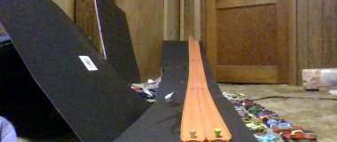
I already made three track base plates at this point, two meter long each. One is going to be the ramp, the other two lay flat. To hold the ramp up, i choose to use one single pole with a detachable baseplate. Easy, small and light. I put a folding hinch under the track and it worked like a charm. So easy to set up, sturdy, and really small for storage. After the bend base plates, this raised the spirits!

Note: A hinge like this locks itself into place when stretched, so this pole stands really sturdy!

And of course a detachable baseplate for stability, nicely spray painted. The red really matches my carpet as you see, preventing any facial damage due to overlooking the plate on the floor:


So, the transition is next. This one is gonna be pretty abstract, because i just realized i didn't make any good pictures when i made this. I'll try to explain: i carved a little layer off the baseplate of the ramp and the first flat baseplate. Mayby a millimeter or two, just as thick as the iron plate i had.

After that, i made something to lock the ramp to the flat baseplate, just like the one under here. (next time i set the track up, i'll try to make a picture of it. This photo is actually of my blu track, but it interlocks exactly the same way)

Than i bended the iron plate in the desired arch an cut it to the right size. A little slip an slide from the side, and it's in. Fully detachable, but sturdy in it's place. Not a single bump!

That's that, we're almost there. Next up are the building of the electronic starting gate, the wrapping up of the finishgate and finally, some small thingies to wrap it up and make the track ready for some good racing. Boy i'm getting excited again.
UPDATE: THE TRANSITION
Here are the actual pics of the transition:


Night 6: Electronic starting gate
Now, this was something new. I had build a starting gate before, but never an electronic one. My idea was to use some "dropping pins", seen many times before on other tracks. Only this time i use a servo to control them. Why a servo you ask? Because (again) it's cheap and it seemed easy to program, after all, this was a first time.
For the design, there were two thing to keep in mind. One: The gate had to be removable, so it could be stored properly wihout a piece of track attached. And two: i saw a great idea somewhere of a big tyre, used as an arch above the line. The Le Mans circuit had one over the track if i remember properly, i really liked it as a kid.
So it's time for shopping again: One hinge, one servo, one aluminium "U" profile, a small tyre, a simple switch, one battery holder and a vga plug to connect it to the finish gate. And of course, the standard mess from the shed, leftover wood, screws, glue, paint.... you know the drill.
A battery holder you say? Yes, the starting gate servo operates on batteries. Why? Because i already had four displays, a lot of led's (i also decided to use the last few unused pins on the arduino to make a traffic light at the starting gate) draining energy and the use of a servo would probably cause instant death to the Arduino, due to a current overload. Never tried it though.
Anyhow, i came up with a wooden plate with a piece of aluminium "U" profile on both sides, which i can slide over the track baseplate to. A piece of the plate was cut loose and connected again with the hinge like this:

As you see, i connected the servo with the moving plate with a piece of metal wire. This worked great but after a few races and some guests players, it turned out that the metal wire did not match with the curiosity of children. Those moving pins work like magnets for little childen fingers, which resulted in a bended metal wire more than once. So later on i strengthened this wire, pics of this will follow at the end of the journal.
Now i needed a small rubber tyre to cut in half. I had to take grannies wheelchair apart for this, but that was soon forgotten ;) China came in again for a good replacement tyre, so i cut it in half and put some nice led's in there to make my own traffic light:


Now i had to fit in the battery compartiment, wire the whole thing and complete the housing so it looked nice and all the parts were protected from food and fingers. Also a switch had to be installed, so the Arduino could ready the state of the startgate and of course start the timer as the gate opens.

Last but not least it was time for granny's tyre, loaded with led's. Glued it on the base of the gate and with some white paint, a snowy electronic starting gate was born. I will not spill all the beans yet, so here is a picture of the nearly finished gate without track. The "U" profiles in the sides slide over the track baseplate. Some felt along the sides prevents scratches and upgrades a good fit, to a perfect fit. Happy happy joy joy!

- DUDE ... that's nice. Love the tire idea, and yes, I believe it was Le Mans that had it. — SpyDude
- Nice building and engineering! Tire is very creative...expect others to yank that idea. One question is weight...all that wood has to be pretty heavy, no? — redlinederby
- Thanks! I saw the idea of the tyre somewhere on the internet long time ago, so the credits for that are not mine. Just bringing it under attention again ;) — DDRacer
- And about weight: Today is actually track day for us, so i put on the scales... — DDRacer
- Start gate: 1,8 kilogram - finish gate: 1,3 kilogram - one trackbase: 3,5 kilogram. So if you want to carry the gates and three trackbases all in one go, it's still under 15 kilograms. Google says that around 33 pounds. — DDRacer
Last stand: Finishing up
All right, almost done! It's about time, because the little big boy is starting to loose patience and wants to race his new toy. First, let's finish the finishgate (uhu). Lots of wire needed to be put thru really small holes...

The final result wil be in my next post, but oh shoot, i forgot something! Because i wanted to use racing software, it's necessary to keep the USB port on the arduino accessible. Crabs! Fortunately there was a lot of room in the electronic box (not), but i managed to get a hole in the box between all the wires. To keep dust outside, i used a rubber plug to cover the hole and, which can be removed when the arduino needs to be connected.

Then we needed a little styling, to make it a real himalaya pass. Everything was painted snowy white and on top of that I used a printable sticker to cover the front of the gate and the electronic box. This really improved the looks and feel.

Created a nice 5 line wire to connect te start an finishgate...

...and for the first test run the track bases needed to be interlocked. Put a rubber band around both of the screws on the side of the track, and BOOM!

After a few practice runs (as said before), there were a few modifations necessary on the starting gate. One is the strengthening of the iron wire, but i also chose to give the serve a little more power so it would open faster. After a few slowmotion test movies, it was really on the edge if the gate was falling faster than the cars started to roll. One extra battery was just enough to be sure and didn't harm the servo.

Ok, i'll shut up now and let the images do the talking:


Thank you for reading, i hope you enjoyed it. Next thing is making a good video, but that's for a next vacation ;)
- Wow, very nicely put together. Should look great in the videos and races. Have fun! — redlinederby
Allright, how did i start!
First step: THE GLOBAL IDEA.
I wanted to make a two lane track, easy to build and store, for my son. Already familiar with blu track, i decided to use normal orange track this time. Why? Because orange track is narrower than blu track, and i preferred a different approach for new champions besides our blu track car heroes. Also because it's narrower, i could use a higher "hill" without the risk of heavy trackbouncing, which can occur with blu track. Other requirements:
- CHEAP and ACCURATE homemade finishline
- CHEAP but TRUSTWORTHY electronic starting gate
- Elapsed time display (I really like this ;)
- Display for finishing place (my son really wanted this option ;)
- Compatible with open software for time administration (we want to race, not administrate)
So... I came up with the idea to use TM1637 displays, because they are really really cheap (1,60 euro a piece, shipping included). I decided to use 4 of them (2 per lane) to show place and time together, and use an Arduino Uno to run the scripts. A basic timer script that could exchange data with racing software was actually quite easy to find, i just had to add a some script for what it had to do when a car didn't get to the finish line (due to a crash or something), and a script to display who became first or second. (EDIT: I also added some script for the electronic starting gate button later on)
Second step: FINISH GATE ELECTRONICS
Electronics are pretty important in this build, so i decided tot start with making them work before doing anything else. As said, i needed an arduino (or arduino look-a-like) to make everyting work together. I ordered this online from china/russia, because it's so darn cheap to get. I also needed a "bread board" for testing, jumper cables, 4x TM1637 displays, 2 white LED's and 2 phototransistors, some resistors, 2x push buttons for starting and resetting the timer, a power adapter, a few plugs to connect everything and last but not least, a case for the arduino. For less than 30 bucks, shipping inlcuded, i got all the electronics (and a lot of extra LED's and resistors) to start writing some code and making the elctronics work.
To be continued...